
Ta sekcja opisuje szczegółowo okna w StarUML?.
- Okno główne
- Menu
- Paski narzędzi
- Okno
- Dialog Box
- Okno podręczne
Rozdział nie został przetłumaczony w całości.
Okno główne
Okno główne w StarUML
Menu Główne
Menu główne znajduje się na górze ekranu. Większość funkcji w StarUML?’ jest dostępnych z menu głównego.
Paski narzędzi
Paski narzędzi są zaraz pod menu głównym. Zawierają często używane opcje.
Obszar przeglądania
Obszar przeglądania jest umieszczony w górnym lewym rogu ekranu. Ten obszar zawiera opcje umożliwiające łatwe przeglądanie elementów komponentów projektu. Zawiera [Model Explorer], który zawiera elementy składowe modelu uporządkowane w odpowiedniej architekturze projektu, oraz [Diagram Explorer], który zawiera diagramy.
Obszar Inspekcji
Obszar inspekcji jest umieszczony w lewym dolnym rogu. Pole to pozwala na edycje szczegółowych własności poszczególnych elementów. Zawiera [Property Editor] do edycji własności, [Documentation Editor] do wykonywania opisów oraz dokumentacji, i [Attachments Editor] pozwalający na dodawanie dodatkowych plików oraz adresów URL.
Information Area
The information area is located in the lower right corner of the screen. This area contains the functions to show various types of information throughout the StarUML? application. This area includes [Output Window] which shows log recordings, [Messages Window] which shows the model search and inspection results.
Diagram Area
The diagram area is located in the upper right corner of the screen. This area contains the functions to edit and manage the diagrams.
Pallet
Located on the left-hand side of the area is Pallet, which contains the elements that can be created.
Menu
This section describes in detail all of the menu items included in StarUML???s main menu.
- File Menu
- Edit Menu
- Format Menu
- Model Menu
- View Menu
- Tools Menu
- Help Menu
- Shortcuts
File Menu
The File menu contains the following menu items.
| Menu Item | Description |
|---|---|
| Creates a new project. | |
| New Project By Approach[Ctrl+I] | Opens the Select New Project dialog box. |
| Opens a project file. | |
| Saves the project file. | |
| Save As[Ctrl+A] | Saves the project as another file. |
| Close | Closes the current project. |
| Unit->Control Unit | Separates and saves the currently selected element as a unit. |
| Unit->Uncontrol Unit | Merges the currently selected unit element to the parent unit (or project). |
| Unit->Delete Unit | Deletes the currently selected unit element |
| Unit->Save Unit | Saves the currently selected unit as a file. |
| Unit->Save Unit As | Saves the currently selected unit as another file. |
| Import->Framework | Imports a framework into the current project. |
| Import->Model Fragment | Imports a model fragment into the current project. |
| Export->Model Fragment | Saves the currently selected element as a model fragment file. |
| Export Diagram[Shift+Ctrl+D] | Saves the currently active diagram as an image file. |
| Page Setup | Configures the page for printing |
| Prints the diagram. | |
| Recent Files | Contains a list of the recently opened files. |
| Exit | Exits the program. |
Edit Menu
The Edit menu contains the following menu items.
| Menu Item | Description |
|---|---|
| Cancels the most recent action performed by the user. | |
| Repeats the most recent action performed by the user. | |
| Copies the selected elements to clipboard and removes them from the current location. | |
| Copies the selected elements to clipboard. | |
| Copy Diagram[Shift+Ctrl+C] | Copies the currently active diagram to clipboard. |
| Copy Diagram as Bitmap[Shift+Ctrl+C] | Copies the currently active diagram to clipboard as Bitmap. |
| Pastes the clipboard contents into the currently selected element (or diagram). | |
| Deletes the selected view elements in the diagram. | |
| Delete From Model[Ctrl+Del] | Deletes the selected model elements. |
| Finds an element. | |
| Select All[Ctrl+A] | Selects all the elements in the current diagram. |
Format Menu
The Format menu contains the following menu items.
| Menu Item | Description |
|---|---|
| Specifies the font for the selected view elements. | |
| Specifies the line color for the selected view elements. | |
| Specifies the fill color for the selected view elements. | |
| Specifies the line style of the selected connection view element as rectilinear. | |
| Specifies the line style of the selected connection view element as oblique. | |
| Shows nothing for the stereotype of the selected view elements. | |
| Shows the stereotype of the selected view elements with text. | |
| Shows the stereotype of the selected view elements with icons. | |
| Shows the stereotype of the selected view elements with decoration. | |
| Suppresses the section that displays the attributes for the selected view elements (e.g. class, usecase, etc.). | |
| Suppresses the section that displays the operations for the selected view elements (e.g. class, subsystem, etc.). | |
| Suppresses the section that displays the attributes for the selected enumerations. | |
| Shows the Word Wrap of the selected view elements. | |
| Shows the parent name of the selected view elements. | |
| Shows the operation signature of the selected view elements (e.g. class, subsystem, etc.). | |
| Shows the property items (e.g. tagged values, changeability attribute, etc.) included in view elements. | |
| Shows the visibility of the compartments of the selected view elements (e.g. attribute compartment, operation compartment, etc.). | |
| Shows the stereotypes of the compartments of the selected view elements (e.g. attribute compartment, operation compartment, etc.). | |
| Automatically resizes the selected view elements. | |
| Alignment-> |
Brings the selected elements to front. |
| Alignment-> |
Sends the selected elements to back. |
| Alignment-> |
Aligns the selected elements to left. |
| Alignment-> |
Aligns the selected elements to right. |
| Alignment-> |
Centers the selected elements horizontally. |
| Alignment-> |
Aligns the selected elements to top. |
| Alignment-> |
Aligns the selected elements to bottom. |
| Alignment-> |
Centers the selected elements vertically. |
| Alignment-> |
Evenly distributes the selected elements horizontally. |
| Alignment-> |
Evenly distributes the selected elements vertically. |
| Lays out the view elements in the current diagram. |
Model Menu
The Model menu contains the following menu items.
| Menu Item | Description |
|---|---|
| Add->… |
Adds a model element. The model elements that can be added under the currently selected model elements are displayed in the sub menu. |
| Add Diagram->… |
Adds a diagram. The diagrams that can be added under the currently selected model elements are displayed in the sub menu. |
|
Opens the collection editor that can be used to edit the child elements of the currently selected model element. |
|
|
Opens the constraint editor that can be used to edit the constraints of the currently selected model element. |
|
|
Opens the tagged value editor that can be used to edit the tagged values of the currently selected model element. |
|
|
Opens the profile manager. |
|
|
Opens the Verify Model dialog box that can be used to inspect the model elements in the current project. |
|
| Convert Diagram->Convert Sequence(Role) to Collaboration(Role) |
Generates a new diagram by converting the currently selected sequence (role) diagram into a collaboration (role) diagram (default Add-In function). |
| Convert Diagram->Convert Collaboration(Role) to Sequence(Role) |
Generates a new diagram by converting the currently selected collaboration (role) diagram into a sequence (role) diagram (default Add-In function). |
View Menu
The View menu contains the following menu items.
| Menu Item | Description |
|---|---|
| Close Diagram | Closes the currently active diagram. |
| Close All Diagrams | Closes all open diagrams. |
| Select In Model Explorer | Shows the currently selected element in the model explorer. |
| Refreshes the current diagram. | |
| Model Explorer | Toggles the Model Explorer on and off. |
| Diagram Explorer | Toggles the Diagram Explorer on and off |
| Properties | Toggles the Properties Editor on and off. |
| Documentations | Toggles the Documentation Editor on and off. |
| Attachments | Toggles the Attachments Editor on and off. |
| Output | Toggles the Output Window on and off. |
| Messages | Toggles the Message Window on and off. |
| Toolbox | Toggles the Toolbox on and off. |
| Zoom-> |
Makes the diagram look larger. |
| Zoom-> |
Makes the diagram look smaller. |
| Zoom-> |
Automatically adjusts the zoom ratio to fit the whole diagram in the window. |
| Zoom->50% | Shows the current diagram at 50% zoom ratio. |
| Zoom->75% | Shows the current diagram at 75% zoom ratio. |
| Zoom->100% | Shows the current diagram at 100% zoom ratio. |
| Zoom->125% | Shows the current diagram at 125% zoom ratio. |
| Zoom->150% | Shows the current diagram at 150% zoom ratio. |
| Zoom->175% | Shows the current diagram at 175% zoom ratio. |
| Zoom->200% | Shows the current diagram at 200% zoom ratio. |
| Toolbars->Standard | Toggles the Standard toolbar on and off. |
| Toolbars->Format | Toggles the Format toolbar on and off. |
| Toolbars->View | Toggles the View toolbar on and off. |
| Toolbars->Alignment | Toggles the Align toolbar on and off. |
Tools Menu
The Tools menu contains the following menu items.
| Menu Item | Description |
|---|---|
| Options… |
Opens the Options dialog box that can be used to edit various environment configuration options. |
| Add-In Manager… |
Opens the Add-In Manager that can be used to manage the additionally installed Add-In programs. |
Help Menu
The Help menu contains the following menu items.
| Menu Item | Description |
|---|---|
Opens the StarUML? help. |
|
| StarUML On the Web | Moves to the StarUML? website. |
| About | Shows the StarUML? information. |
Shortcuts
StarUML? provides shortcuts to menu functions. The shortcuts can increase efficiency and convenience in software modeling.
Shortcuts List
| Shortcut | Menu Item |
|---|---|
| Del | Delete |
| F1 | |
| F5 | Refresh |
| F6 | Browser Window |
| F7 | Inspector Window |
| F8 | Information Window |
| F9 | Verify Model |
| Ctrl+F4 | Close Diagram |
| Ctrl+F5 | Collection Editor |
| Ctrl+F6 | Constraint Editor |
| Ctrl+F7 | Tagged Values |
| Ctrl+A | Select All |
| Ctrl+B | Oblique |
| Ctrl+C | Copy |
| Ctrl+F | Find |
| Ctrl+I | Select New Project |
| Ctrl+L | Rectilinear |
| Ctrl+M | Show in Model Explorer |
| Ctrl+N | New Project |
| Ctrl+O | Open |
| Ctrl+P | |
| Ctrl+S | Save |
| Ctrl+V | Paste |
| Ctrl+X | Cut |
| Ctrl+Y | Redo |
| Ctrl+Z | Undo |
| Ctrl+Del | Delete Model |
| Shift+Ctrl+F4 | Close All Diagrams |
| Shift+Ctrl+A | Suppress Attributes |
| Shift+Ctrl+C | Copy Diagram |
| Shift+Ctrl+D | Export Diagram |
| Shift+Ctrl+E | Decoration(Stereotype Display) |
| Shift+Ctrl+I | Icon (Stereotype Display) |
| Shift+Ctrl+L | Suppress Literals |
| Shift+Ctrl+N | None (Stereotype Display) |
| Shift+Ctrl+O | Suppress Operations |
| Shift+Ctrl+S | Save As |
| Shift+Ctrl+T | Text (Stereotype Display) |
Toobars
This section describes in detail all of the toolbar items in StarUML?.
- Standard Toolbar
- Format Toolbar
- View Toolbar
- Align Toolbar
- Pallet Toolbar
Standard Toolbar
The Standard toolbar contains the following functions.
| Toolbar | Description |
|---|---|
| Creates a new project. | |
| Opens a project file. | |
| Saves the project file | |
| Prints the diagram. | |
| Copies the selected elements to clipboard and removes them from the current location. | |
| Copies the selected elements to clipboard. | |
| Pastes the clipboard contents into the currently selected element (or diagram). | |
| Deletes the selected view elements in the diagram. | |
| Cancels the most recent action performed by the user. | |
| Repeats the most recent action performed by the user. | |
| Finds an element. | |
|
Opens the collection editor that can be used to edit the child elements of the currently selected model element. |
|
|
Opens the constraint editor that can be used to edit the constraints of the currently selected model element. |
|
|
Opens the tagged value editor that can be used to edit the tag definitions of the currently selected model element. |
|
|
Opens the profile manager. |
|
|
Opens the Verify Model dialog box that can be used to inspect the model elements in the current project. |
Format Toolbar
The Format toolbar contains the following functions.
| Tool | Description |
|---|---|
| (Combo) Font Name | Specifies the font name for the selected view elements. |
| (Combo) Font Size | Specifies the font size for the selected view elements. |
| Specifies the font for the selected view elements. | |
| Specifies the line color for the selected view elements. | |
| Specifies the fill color for the selected view elements. | |
| Automatically resizes the selected view elements. | |
| Specifies how the stereotypes will be shown for the selected view elements. | |
| Specifies how the extended notation will be shown for the selected view elements. | |
| Specifies the line style for the selected connection view elements. | |
| Suppresses the section that displays the attributes for the selected view elements (e.g. class, usecase, etc.). | |
| Suppresses the section that displays the operations for the selected view elements (e.g. class, subsystem, etc.). | |
| Suppresses the section that displays the attributes for the selected enumerations. | |
| Shows the word wrap of the selected view elements. | |
| Shows the parent name of the selected view elements. | |
| Shows the operation signature of the selected view elements (e.g. class, subsystem, etc.). | |
| Shows the property items (e.g. tagged values, changeability attribute, etc.) included in view elements. | |
| Shows the visibility of the compartments of the selected view elements (e.g. attribute compartment, operation compartment, etc.). | |
| Shows the stereotype of the compartments of the selected view elements (e.g. attribute compartment, operation compartment, etc.). |
??
View Toolbar
The View toolbar contains the following functions.
| Tool | Description |
|---|---|
| (Combo) Zoom |
Selects the zoom ratio for the current diagram. |
|
Makes the diagram look larger. |
|
|
Makes the diagram look smaller. |
|
|
Automatically adjusts the zoom ratio to fit the whole diagram in the window. |
|
|
Refreshes the current diagram. |
Align Toolbar
The Align toolbar contains the following functions.
| Tool | Description |
|---|---|
|
Lays out the view elements in the current diagram. |
|
|
Brings the selected elements to front. |
|
|
Sends the selected elements to back. |
|
|
Aligns the selected elements to left. |
|
|
Aligns the selected elements to right. |
|
|
Centers the selected elements horizontally. |
|
|
Aligns the selected elements to top. |
|
|
Aligns the selected elements to bottom. |
|
|
Centers the selected elements vertically. |
|
|
Evenly distributes the selected elements horizontally. |
|
|
Evenly distributes the selected elements vertically. |
Pallet Toolbar
The Pallet toolbar contains the following functions for selecting and creating elements in the diagram.
Common Pallet Tool
The following functions are always available in the Pallet toolbar regardless of the diagram types.
| Tool | Description |
|---|---|
|
The most basic tool that selects, moves or resizes an element in the diagram. |
|
| Creates a note element in the current diagram. | |
| Links a note in the current diagram to another element. | |
| Creates a string element in the current diagram. | |
| Create a figure of rectangle in the current diagram. | |
| Creates a figure of ellipse in the current diagram. | |
| Creates a figure of rounded rectangle in the current diagram. |
Pallet Tool by Diagram Types
The following functions create elements by diagram types.
| Tool | Description | Diagram |
|---|---|---|
|
The most basic tool that selects, moves or resizes an element in the diagram. |
All diagrams |
|
|
Creates a subsystem element in the current diagram. |
Class Diagram |
|
|
Creates a package element in the current diagram.. |
Class Diagram, Component Diagram, Deployment Diagram, UseCase Diagram |
|
|
Creates a class element in the current diagram. |
Class Diagram, Composite Diagram |
|
|
Creates an interface element in the current diagram. |
Class Diagram, Component Diagram, Composite Diagram |
|
|
Creates an enumeration element in the current diagram. |
Class Diagram |
|
|
Creates a signal element in the current diagram. |
Class Diagram |
|
|
Creates an exception element in the current diagram. |
Class Diagram |
|
|
Creates a component element in the current diagram. |
Component Diagram |
|
|
Creates a component instance element in the current diagram. |
Component Diagram |
|
|
Creates a node element in the current diagram. |
Deployment Diagram |
|
|
Creates a node instance element in the current diagram. |
Component Diagram, Deployment Diagram |
|
|
Creates a artifact in the current diagram. |
UseCase Diagram |
|
|
Creates a usecase element in the current diagram. |
UseCase Diagram |
|
|
Creates an actor element in the current diagram. |
UseCase Diagram |
|
|
Creates an system boundary in the current diagram. |
UseCase Diagram |
|
|
Creates an object element in the current diagram. |
Class Diagram, Sequence Diagram, Collaboration Diagram |
|
|
Creates a Part element with a Classifier in the current diagram. |
Class Diagram, Component Diagram, Deployment Diagram, Composite Diagram |
|
|
Creates a Port element with a Classifier in the current diagram. |
Class Diagram, Component Diagram, Deployment Diagram, Composite Diagram |
|
|
Creates a ClassifierRole element in the current diagram. |
Sequence Role Diagram, Collaboration Role Diagram |
|
|
Creates a Combined Fragment element in the current diagram. |
Sequence Diagram, Sequence Role Diagram, Collaboration Diagram, Collaboration Role Diagram |
|
|
Creates a Interaction Operand element with a Combined Fragment in the current diagram. |
Sequence Diagram, Sequence Role Diagram, Collaboration Diagram, Collaboration Role Diagram |
|
|
Creates a Frame element in the current diagram |
Sequence Diagram, Sequence Role Diagram, Collaboration Diagram, Collaboration Role Diagram |
|
|
Creates a CompositeState element in the current diagram. |
Statechart Diagram |
|
|
Creates a SubmachineState element in the current diagram. |
Statechart Diagram |
|
|
Creates an InitialState (Pseudostate) element in the current diagram. |
Statechart Diagram, Activity Diagram |
|
|
Creates a FinalState element in the current diagram. |
Statechart Diagram, Activity Diagram |
|
|
Creates a DeepHistory(FlowFinalState) element in the current diagram. |
Statechart Diagram, Activity Diagram |
|
|
Creates a Choice (Pseudostate) element in the current diagram. |
Statechart Diagram |
|
|
Creates a Junction (Pseudostate) element in the current diagram. |
Statechart Diagram |
|
|
Creates a ShallowHistory (Pseudostate) element in the current diagram. |
Statechart Diagram |
|
|
Creates a DeepHistory (Pseudostate) element in the current diagram. |
Statechart Diagram |
|
|
Creates a Synchronization (Pseudostate) element in the current diagram. |
Statechart Diagram, Activity Diagram |
|
|
Creates an ActionState element in the current diagram. |
Activity Diagram |
|
|
Creates a Subactivity State element in the current diagram. |
Activity Diagram |
|
|
Creates a Decision (Pseudostate) element in the current diagram. |
Activity Diagram |
|
|
Creates a ObjectFlowState element in the current diagram. |
Activity Diagram |
|
|
Creates a SignalAcceptState element in the current diagram. |
Activity Diagram |
|
|
Creates a SignalSendState element in the current diagram. |
Activity Diagram |
|
|
Creates a Swimlane by vertical solid lines in the current diagram. |
Activity Diagram |
|
|
Creates a Swimlane by horizontal solid lines in the current diagram. |
Activity Diagram |
|
|
Links a semantic association between two classes in the current diagram. |
Class Diagram, Component Diagram, Deployment Diagram, UseCase Diagram |
|
|
Links a semantic association between two classes in the current diagram. |
Class Diagram, Deployment Diagram, UseCase Diagram |
|
|
Links a semantic association between two classes in the current diagram. |
Class Diagram |
|
|
Links a semantic association between two classes in the current diagram. |
Class Diagram |
|
|
Links a generalized element and a specialized element with a generalization relation in the current diagram. |
Class Diagram, UseCase Diagram |
|
|
Links two elements with a dependency relation in the current diagram. |
Class Diagram, Component Diagram, Deployment Diagram, UseCase Diagram, Composite Diagram |
|
|
Links a specification element and its implementation element with a realization relation in the current diagram. |
Class Diagram, Component Diagram, Composite Diagram |
|
|
Links a class and an association in the current diagram so that the association itself can have the significance of a class. |
Class Diagram |
|
|
Links two UseCases with an Include relation in the current diagram so that one UseCase includes the other UseCase behaviors. |
UseCase Diagram |
|
|
Links two UseCases with an Extend relation in the current diagram so that one UseCase can be extended with the behaviors defined in the other UseCase. |
UseCase Diagram |
|
|
Links two roles with an AssociationRole in the current diagram. |
Collaboration Role Diagram |
|
|
Creates an AssociationRole from one role to the same role in the current diagram. |
Collaboration Role Diagram |
|
|
Links two objects in the current diagram. |
Class Diagram, Collaboration Diagram |
|
|
Links an object with itself in the current diagram. |
Class Diagram, Collaboration Diagram |
|
|
Defines a message between two roles in the current diagram. |
Sequence Role Diagram, Collaboration Role Diagram |
|
|
Defines a message between two roles in the current diagram. |
Sequence Role Diagram, Collaboration Role Diagram |
|
|
Creates a message from a role to the same role in the current diagram. |
Sequence Role Diagram, Collaboration Role Diagram |
|
|
Defines a stimulus between two objects in the current diagram. |
Sequence Diagram, Collaboration Diagram |
|
|
Defines a stimulus between two objects in the current diagram. |
Sequence Diagram, Collaboration Diagram |
|
|
Creates a stimulus from an object to the same object in the current diagram. |
Sequence Diagram, Collaboration Diagram |
|
|
Links a source state and a target state with a transition in the current diagram. |
Statechart Diagram, Activity Diagram |
|
|
Links an original state and a target state with a transition in the current diagram. |
Statechart Diagram, Activity Diagram |
|
|
Links a original feature and a target feature with a connector in the current diagram. |
Class Diagram, Component Diagram, Deployment Diagram, Composite Diagram |
Viewers
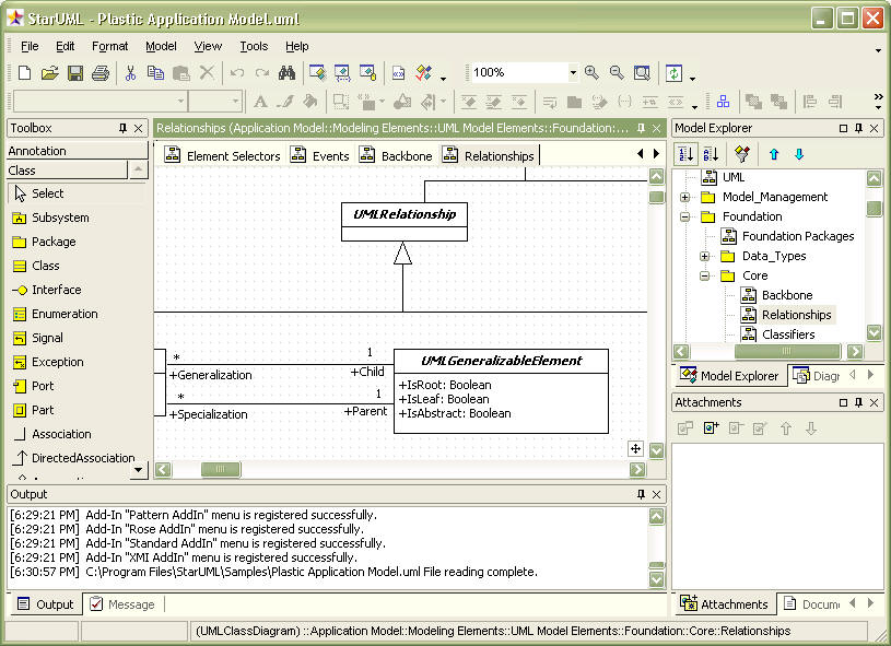
Model Explorer
The Model Explorer supports the user to effectively manage and explore the model elements by showing them in hierarchical structures. Select the [Model Explorer] tab in the [Browser] area to open the Model Explorer.
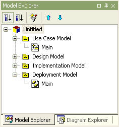
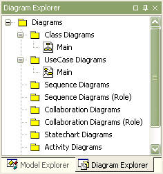
Diagram Explorer
The Diagram Explorer supports the user to effectively manage and explore the diagrams by listing them by their types. Select the [Diagram Explorer] tab in the [Browser] area to open the Diagram Explorer.
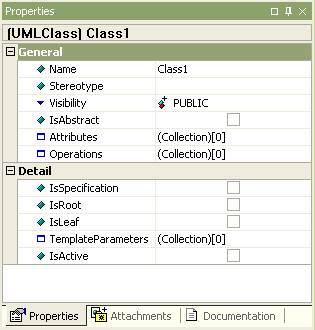
Property Editor
The Property Editor is used for editing the detailed properties of the currently selected model element. Select the [Properties] tab in the [Inspector] area to open the Property Editor.
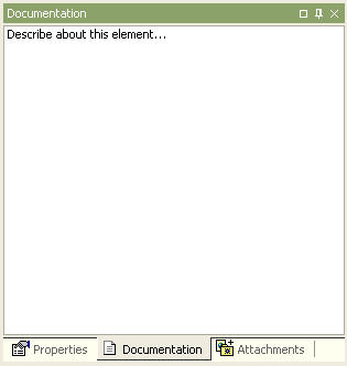
Documentation Editor
The Documentation Editor is used for recording additional descriptions of the currently selected element. Select the [Documentation] tab in the [Inspector] area to open the Documentation Editor.
Attachments Editor
The Attachments Editor allows the user to attach files or web URLs to a specific element. Select the [Attachments] tab in the [Inspector] area to open the Attachments Editor.
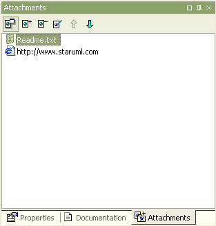
Attachment List
Shows a list of the files or URLs attached to the element.
Open Button
Opens the selected attachment file or URL with the associated program. For example, if a .doc file is selected, it is automatically opened in Microsoft Word, and if a web address such as http://www.staruml.com is selected, it is opened in the web browser.
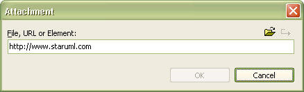
Add Button
Attaches a new file or URL. Click this button to open the Attachment Item dialog box.
Remove Button
Removes the selected item from the attachment list.
Edit Button
Edits the selected item from the attachment list. The Attachment Item Editor can be used to change the file name or enter another URL.
Move Up Button
Moves the selected item up in the attachment list.
Move Down Button
Moves the selected item down in the attachment list.
Attachment Item Dialog Box
Edits the attachment item name. Enter a URL or pathname for a file. The button on the right can be used to select a file.
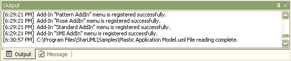
Output Window
The Output Window keeps and shows a record of the events in StarUML?. Select the [Output] tab in the [Information] area to open the Output Window.
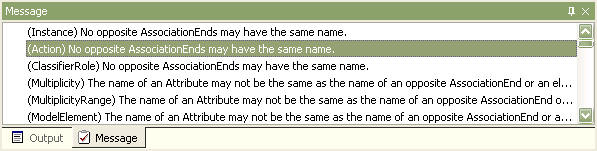
Messages Window
The Message Window shows the results of element search or software model inspection. Select the [Messages] tab in the [Information] area to open the Message Window.
Dialogs
Collection Editor
The Collection Editor is used for managing a list of child elements for a specific element.
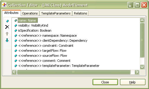
Tab
Shows collections (a list of child elements contained in the current element) contained in the element by tabs. Different types of elements have different collections, and therefore have different tabs. For example, Class element has tabs for Attributes and Operations. The Relations tab is always present regardless of the element type.
Collection Element List
Shows a list of the child elements. Select an element here and edit it using the property editor, documentation editor, and attachment editor in the inspector area. For showing element stereotype, visibility/stereotype, etc., please refer to the section on General Configurations, in Environment Configurations.
Add Button
Creates a new element and adds it to the list. This button may connect existing elements instead of creating a new element (e.g. Residents, DeployedComponents, RaisedSignals).
Delete Button
Deletes the selected element in the collection element list. This button may remove the element from the list instead of deleting it (e.g. Residents, DeployedComponents, RaisedSignals).
Move Up Button
Moves the selected element up in the collection element list.
Move Down Button
Moves the selected element down in the collection element list.
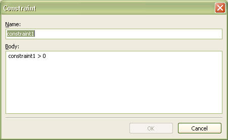
Constraint Editor
The Constraint Editor is used for managing the constraints for elements.

Constraints
Shows the names and contents of the constraints for elements.
Add
Adds a new constraint to the element. This button opens the Constraints dialog box.
Delete
Deletes the selected constraint in the constraints list.
Edit
Edits the selected constraint in the constraints list.
Move Up
Moves the selected constraint up in the constraints list.
Move Down
Moves the selected constraint down in the constraints list.
Constraint Dialog Box
This is used for adding a new constraint or editing the name and/or contents of existing constraints in the Constraint Editor. Enter the name of the constraint in the [Name] field and enter the contents of the constraint in the [Expression] field. The user may freely enter any contents or write in the UML OCL (Object Constraint Language).
Tagged Value Editor
The Tagged Value Editor is used for editing the tagged values that can be added to specific elements.
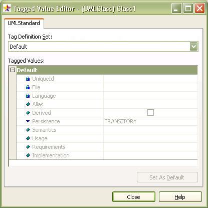
Profile Tab
By default, tagged values are defined in profiles. If there is a profile that contains the tagged values which can be applied to the currently selected element, it is shown as a tab. The tag definitions defined in the profile are displayed in the [Tag Definition Set] and [Tagged Values] fields.
Tag Definition Set
Shows the tag definition set that can be applied to the currently selected element. The tagged values included in this set are displayed in the [Tagged Values] field.
Tagged Values
Lists the definitions and their values included in the tag definition set selected in [Tag Definition Set]. The user may directly change the values.
Set As Default
Every tag definition has a default value. Select a tag definition in [Tagged Values] and click this button to clear the changed value and set it back to the default value.
Profile Manager
The Profile Manager can be used for including or excluding the UML profiles for the current project.
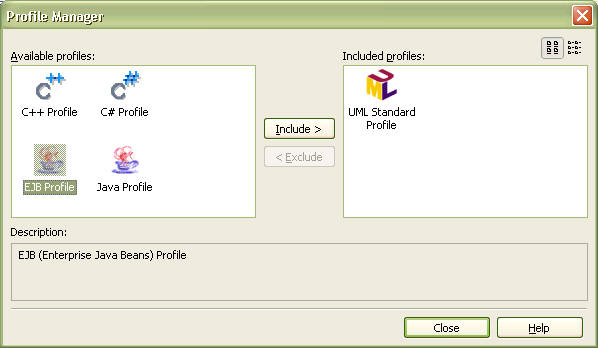
Available profiles
Shows a list of the UML profiles registered for use in StarUML?. Profiles currently in use by the current project are not shown here.
Include profiles
Shows a list of the UML profiles in use by the current project.
Large Icon/Small Icon Button
Toggles the profile list icon size between large and small. Select the Small Icon Button if the profile names are only partially shown and difficult to read.
Include
Includes the profile selected in the available profile list for use by the current project.
Exclude
Excludes the profile selected in the included profile list so that it is no longer used by the current project.
Add-In Manager
The Add-In Manager can be used to view a list of the installed Add-Ins and to enable or disable the Add-Ins.
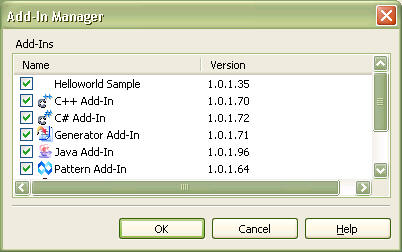
Add-Ins List
Shows a list of the installed Add-Ins. The user can check or uncheck each item to enable or disable the respective Add-In.
 Note
Note
- The list of Add-Ins in the Add-In Manager window may vary according to the user??s installation environment.
Select New Project Dialog Box
The Select New Project dialog box provides various selection methods when creating a new project. The New Project dialog box consists of three pages: Select Approach, Open Existing File, and Open Recent File.
Approaches
The user can apply a specific approach for creating a new project.
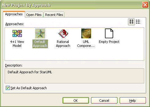
- Approaches: The approaches list displays the names and icons of the registered approaches. Select the ??Empty Project?? item if no approach is needed.
- Large Icon/Small Icon Button: This toggles the icon size for the approach list. Select the small icon button if the approach names are shortened and difficult to read.
- Description: This area shows a brief description of the approach item selected from the list.
- Use the selected Approach by default : Select an approach from the list and check this check box to set the approach as the default approach. The default approach is applied when creating a new project by selecting the [File] -> [New] -> [New Project] menu.
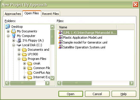
Open Files
The user can open a previously created file. The tree view on the left shows the user system??s folder structure, and the file list area on the right shows the project files in the selected folder. Select a file from this file list and click the [Open] button to open the selected file.
Recent Files
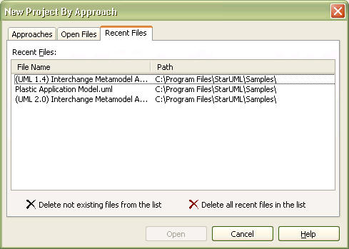
The user can see a list of the recently edited files and open them.
- Recently modified files: Shows a list of the recently edited files.
- Remove non-existent files from the list: Checks for files that no longer exist and removes them from the recent files list.
- Clear the recent files list: Clears all the files in the recent file list. The recent file list in the system registry is deleted.
Import Framework Dialog Box
The Import Framework dialog box allows the user to select an available framework and load it to the current project.
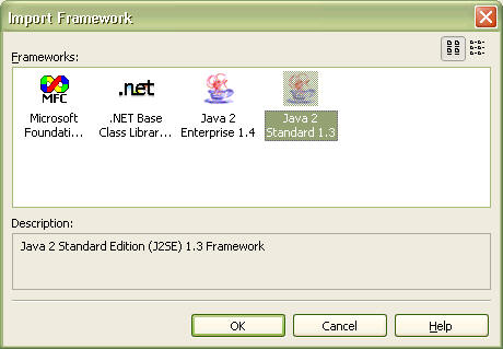
Frameworks list
The frameworks list displays the names and icons of the registered frameworks. Select a framework to load.
Large Icon/Small Icon Button
This toggles the icon size for the framework list. Select the small icon button if the framework names are shortened and difficult to read.
Description
This area shows a brief description of the framework item selected from the list.
Page Setup Dialog Box
The Page Setup dialog box allows the user to specify what and how diagram information is printed, the paper orientation, margins, outlines, etc.
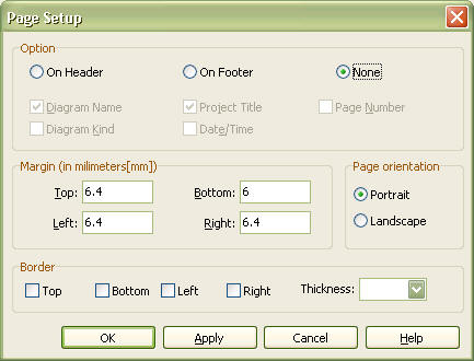
Option
The user can specify some of the diagram information to be printed.
- On Header : Prints the diagram information in the page header.
- On Footer : Prints the diagram information in the page footer.
- None : Does not print the diagram information.
- Diagram Name : Prints the diagram name.
- Project Title : Prints the project name of the diagram.
- Page Number : Prints the page number.
- Diagram Kind : Prints the diagram kind.
- Date/Time :Prints the current date and time.
Margin
The user can specify the top, bottom, left, and right page margins in millimeters.
Page orientation
The user can specify whether to print the page in portrait or landscape.
Border
The user can specify how the page border will be printed. Select top, bottom, left, or right for drawing border and specify the border thickness.
Print Dialog Box
The Print dialog box appears when the user prints a diagram. The user can select and specify various options related to printing.
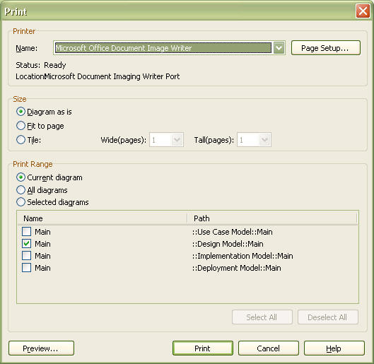
Printer
The user can configure the printer-related options.
- Name : Select a printer to use from the installed printers.
- Status : Indicates the status of the selected printer.
- Location : Indicates the location of the selected printer.
- Page Setup : Opens the Page Setup dialog box.
Size
Specifies the size of the diagram to print.
- Diagram as is : Prints the diagram in its original size. The diagram is printed in multiple pages if it does not fit in one page.
- Fit to page : Prints the diagram to fit in one page. This option prevents printing of multiple pages if the diagram is large.
- Tile : Prints the diagram to fit in multiple pages. The user can specify the number of pages to print by width and height (e.g. 3 pages wide and 4 pages tall = total 12 pages).
Print Range
Specifies the range of the diagram to print.
- Current diagram : Prints only the currently active diagram.
- All diagrams : Prints all of the diagrams in the current project.
- Selected diagrams : Prints only the selected diagram. The [Select All] button selects all diagrams, and the [Deselect All] button deselects all diagrams.
Preview
Opens the Preview dialog box.
Print Preview Dialog Box
The Print Preview dialog box allows the user to preview the print result before actually printing the diagram.
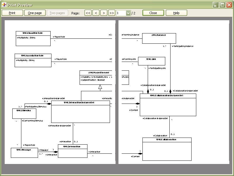
Starts printing.
One Page / Two Pages
Toggles preview by one page or two pages.
<<, <, >, >>
Allows navigation to the first page, previous page, next page, and last page.
Page Selection
The user can move to a specific page by directly entering the page number.
Find Dialog Box
The Find dialog box allows the user to find elements quickly and easily.
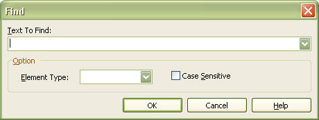
Text to Find
Enter the full or partial string for the element to find. The user can also select from the previously entered strings.
Option-Element Type
This specifies the range of elements to find. Available ranges: ??All elements??, Model, Subsystem, Package, Class, Interface, Enumeration, Signal, Exception, Component, Node, Instance, UseCase, and Actor.
Option-Case Sensitive
This specifies lowercase or uppercase for the element to find.
Verify Model Dialog Box
The Verify Model dialog box is used to inspect the model elements and their definitions.
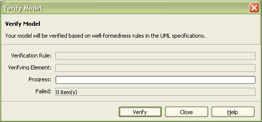
Verification Rule
Shows the verification rule currently being applied.
Verifying Element
Shows the name of the element currently being verified.
Progress
Visually displays the progress of the verification.
Failed
Indicates the number of the elements that failed the verification.
Options Dialog Box
The Options dialog box lists the various option items for environment configuration of StarUML? and allows the user to edit them.
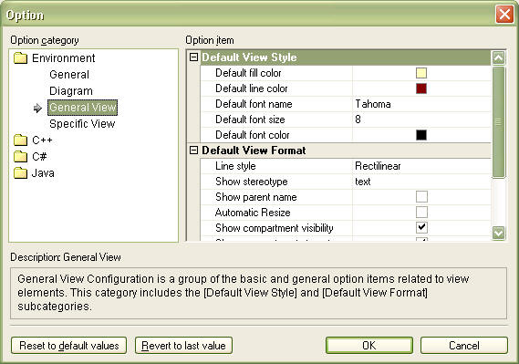
Option category
This list shows the option categories. The top category is ??Environment?? which contains the sub-categories ??General??, ??Diagram??, ??General View??, and ??Specific View??. Additional option categories may be present depending on the module of StarUML?.
Option item
Shows the option items contained in the selected option category. The option values can be edited.
Description
Shows a brief description of the selected option category or item.
Reset to default values
Sets the selected option item value to the default value.
Revert to last value
Reverts the selected option item value to the last saved value.
??
Select Stereotype Dialog Box
The Select Stereotype dialog box appears when the user needs to specify a stereotype for the selected element. The stereotype can be entered directly or selected from the list.
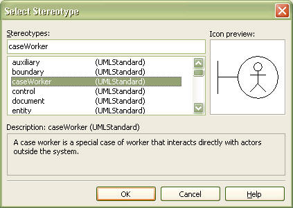
Stereotypes
The user can directly enter the stereotype. If a stereotype has been registered, it is indicated in the stereotype list.
Stereotypes List
Shows the stereotypes defined in the UML profiles that are in use by the current project. The name of the stereotype and the name of the project that contains it are shown together. The user can select a stereotype from the list.
Icon preview
The icon is shown if the selected stereotype is associated with an icon.
Description
Shows the description for the selected stereotype.
Select Element Dialog Box
The Select Element dialog box allows the user to select an element from the hierarchical structure of the project elements. The Select Element dialog box appears when the user needs to assign an element at the property editor, collection editor, etc. Unlike the Element List dialog box, the Select Element dialog box lists the elements in a hierarchical structure.
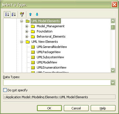
Dialog Box Title
The dialog box title changes according to the type of the element to be selected. An appropriate title is displayed for defining the attribute type, or the object type (i.e., Classifier).
Element List
Shows the available elements. For example, only the StateMachine elements are displayed when selecting a StateMachine element.
Data Types
Shows the available data types. The data types shown here are those defined in the UML profiles which are in use by the current project. This list may not be shown if a data type does not need to be specified.
Do not specify??
Check this to specify nothing. This actually assigns a null value.
Selected Element
The bottom part of the dialog box shows the full pathname of the selected element. This information can be used to verify which element is currently selected.
Element List Dialog Box
The Element List dialog box allows the user to select an element from a list. The Select Element dialog box appears when the user needs to assign an element to a specific property at the property editor, collection editor, etc. Unlike the Select Element dialog box, the Element List dialog box lists the elements in a one-dimensional list.
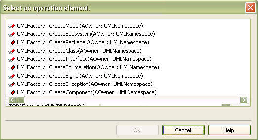
Dialog Box Title
The dialog box title changes according to the type of the element to be selected. An appropriate title is displayed for selecting a StateMachine, or for assigning a component in a node.
Element List
Shows the available elements. For example, only the StateMachine elements are displayed when selecting a StateMachine element.
Do not specify??
Check this to specify nothing. This actually assigns a null value.
Model Filtering Dialog Box
The Model Filter dialog box can be used to show or hide specific elements in the model explorer.
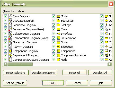
Element to show
Shows all the elements that can be displayed in the model explorer. Only those checked are displayed in the model explorer.
Select Relations
Selects all the relationship elements (Transition, Dependency, Association, AssociationClass, Generalization, Link, AssociationRole, Stimulus, Message, Include, Extend, and Realization) from the elements list.
Deselect Relations
Deselects all the relation elements.
Select All
Selects all elements.
Deselect All
Deselects all elements.
Set As Default
Selects the elements set as default by the program.
Quick Dialogs
This section describes in detail all the quick dialogs available in StarUML?.
- General Quick Dialog
- Subsystem Quick Dialog
- Classifier Quick Dialog
- Enumeration Quick Dialog
- Literal Quick Dialog
- Attribute Quick Dialog
- Operation Quick Dialog
- AssociationEnd Quick Dialog
- Object Quick Dialog
- ClassifierRole Quick Dialog
- Message/Stimulus Quick Dialog
- State Quick Dialog
- Action Quick Dialog
- Note/Text Quick Dialog
General Quick Dialog
General Quick Dialog is the most general form of the quick dialogs. This is used for most of the elements. This appears when an element is double-clicked in diagram. Hitting the [Enter] key or clicking outside the quick dialog applies the changes.
![]()
Visibility Button 
Element visibility can be selected from ![]() Public,
Public, ![]() Protected,
Protected, ![]() Private, and
Private, and ![]() Package.
Package.
Edit Field 
Element name, visibility and stereotype can be entered in the edit field according to the syntax.
Syntax
<< stereotype >> visibility name
- << stereotype >> : Enter the stereotype name. This may be omitted.
- visibility : Enter the character that corresponds to the element??s visibility (??+??: public, ??#??: protected, ??-??: private, ??~??: package). This may be omitted.
- name : Enter the element??s name.
Elements Applied
Subsystem Quick Dialog
Subsystem Quick Dialog is applied only to subsystem elements. This appears when a subsystem is double-clicked in a diagram. Hitting the [Enter] key or clicking outside the quick dialog applies the changes.
![]()
Visibility Button
Subsystem visibility can be selected from ![]() Public,
Public, ![]() Protected,
Protected, ![]() Private, and
Private, and ![]() Package.
Package.
Edit Field
Subsystem name, visibility and stereotype can be entered in the edit field according to the syntax.
Syntax
<< stereotype >> visibility name
- << stereotype >> : Enter the stereotype name. This may be omitted.
- visibility : Enter the character that corresponds to the subsystem??s visibility (??+??: public, ??#??: protected, ??-??: private, ??~??: package). This may be omitted.
- name : Enter the subsystem??s name.
Add Operation Button
Creates and adds a new operation.
Elements Applied
Subsystem
Classifier Quick Dialog
Classifier Quick Dialog is applied only to the elements that fall in the Classifier category (e.g. Class, Actor, Signal, …). Hitting the [Enter] key or clicking outside the quick dialog applies the changes.
![]()
Visibility Button
Element visibility can be selected from ![]() Public,
Public, ![]() Protected,
Protected, ![]() Private, and
Private, and ![]() Package.
Package.
Edit Field 
Element name, visibility and stereotype can be entered in the edit field according to the syntax.
Syntax
<< stereotype >> visibility name
- << stereotype >> : Enter the stereotype name. This may be omitted.
- visibility : Enter the character that corresponds to the element??s visibility (??+??: public, ??#??: protected, ??-??: private, ??~??: package). This may be omitted.
- name : Enter the element??s name.
Add Attribute Button 
Creates and adds a new attribute.
Add Operation Button
Creates and adds a new operation.
Elements Applied
Class, Interface, Signal, Exception, Actor, UseCase, Artifact
Enumeration Quick Dialog
Enumeration Quick Dialog is applied only to enumeration elements. This appears when an enumeration is double-clicked in a diagram. Hitting the [Enter] key or clicking outside the quick dialog applies the changes.
![]()
Visibility Button
Enumeration visibility can be selected from ![]() Public,
Public, ![]() Protected,
Protected, ![]() Private, and
Private, and ![]() Package.
Package.
Edit Field
Enumeration name, visibility and stereotype can be entered in the edit field according to the syntax.
Syntax
<< stereotype >> visibility name
- << stereotype >> : Enter the stereotype name. This may be omitted.
- visibility : Enter the character that corresponds to the enumeration??s visibility (??+??: public, ??#??: protected, ??-??: private, ??~??: package). This may be omitted.
- name : Enter the enumeration??s name.
Add Literal Button 
Creates and adds a new literal.
Add Operation Button
Creates and adds a new operation.
Elements Applied
Enumeration
Attribute Quick Dialog
Attribute Quick Dialog is applied only to attribute elements. This appears when an attribute is double-clicked in a diagram. Hitting the [Enter] key or clicking outside the quick dialog applies the changes.
![]()
Visibility Button
Attribute visibility can be selected from ![]() Public,
Public, ![]() Protected,
Protected, ![]() Private, and
Private, and ![]() Package.
Package.
Edit Field
Attribute stereotype, visibility, name, type, multiplicity, order and default value can be entered in the edit field according to the syntax.
Syntax
<< stereotype >> visibility name : type = initialvalue
- << stereotype >> : Enter the stereotype name. This may be omitted.
- visibility : Enter the character that corresponds to the attribute??s visibility (??+??: public, ??#??: protected, ??-??: private, ??~??: package). This may be omitted.
- name : Enter the attribute??s name.
- : type : Enter the attribute??s type. This may be omitted.
- = initialvalue : Enter the attribute??s default value. This may be omitted.
 Note
Note
- Quick Dialog doesn’t supports a part of [multiplicity ordered] among attribute notations in UML Specification. Because it has been used part of type as [] symbol to the meaning of array.
Add Button
This adds a new attribute in the next location. Hitting [Ctrl + Enter] has the same effect. To insert in the current location, hit the [Ins] key.
Delete Button
This deletes the attribute. Hitting [Ctrl + Del] has the same effect.
Move Up Button 
This moves the current attribute up. Hitting [Ctrl + Up] has the same effect. To edit the upper attribute, just hit the [Up] key.
Move Down Button 
This moves the current attribute down. Hitting [Ctrl + Down] has the same effect. To edit the lower attribute, just hit the [Down] key.
Elements Applied
Attribute
Operation Quick Dialog
Operation Quick Dialog is applied only to operation elements. This appears when an operation is double-clicked in a diagram. Hitting the [Enter] key or clicking outside the quick dialog applies the changes.
![]()
Visibility Button
Operation visibility can be selected from ![]() Public,
Public, ![]() Protected,
Protected, ![]() Private, and
Private, and ![]() Package.
Package.
Edit Field 
Operation stereotype, visibility, name, parameter, and return type can be entered in the edit field according to the syntax.
Syntax
<< stereotype >> visibility name( parameters ) : returntype
- << stereotype >> : Enter the stereotype name. This may be omitted.
- visibility : Enter the character that corresponds to the operation??s visibility (??+??: public, ??#??: protected, ??-??: private, ??~??: package). This may be omitted.
- name : Enter the operation??s name
- ( parameters ) : Enter the operation??s parameters. Parameters follow the syntax of ??direction name : type?? and the parameters are separated by comma (,). Parameter relay direction is indicated by ??direction??; it can be ??in??, ??inout??, or ??out??. Parameter name is indicated by ??name??, and parameter type is indicated by ??type??. This may be omitted.
- : returntype : Enter the operation??s return type. This may be omitted.
Add Button
This adds a new operation in the next location. Hitting [Ctrl + Enter] has the same effect. To insert in the current location, hit the [Ins] key.
Delete Button
This deletes the operation. Hitting [Ctrl + Del] has the same effect.
Move Up Button
This moves the current operation up. Hitting [Ctrl + Up] has the same effect. To edit the upper operation, just hit the [Up] key.
Move Down Button
This moves the current operation down. Hitting [Ctrl + Down] has the same effect. To edit the lower operation, just hit the [Down] key.
Elements Applied
Operation
Literal Quick Dialog
Literal Quick Dialog is applied only to literal elements. This appears when a literal is double-clicked in a diagram. Hitting the [Enter] key or clicking outside the quick dialog applies the changes.
![]()
Visibility Button
Literal visibility can be selected from ![]() Public,
Public, ![]() Protected,
Protected, ![]() Private, and
Private, and ![]() Package.
Package.
Edit Field 
Literal name, visibility and stereotype can be entered in the edit field according to the syntax.
Syntax
<< stereotype >> visibility name
- << stereotype >> : Enter the stereotype name. This may be omitted.
- visibility : Enter the character that corresponds to the literal??s visibility (??+??: public, ??#??: protected, ??-??: private, ??~??: package). This may be omitted.
- name : Enter the literal??s name.
Add Button
This adds a new literal in the next location. Hitting [Ctrl + Enter] has the same effect. To insert in the current location, hit the [Ins] key.
Delete Button
This deletes the literal. Hitting [Ctrl + Del] has the same effect.
This moves the current literal up. Hitting [Ctrl + Up] has the same effect. To edit the upper literal, just hit the [Up] key.
Move Up Button
This moves the current literal up. Hitting [Ctrl + Up] has the same effect. To edit the upper literal, just hit the [Up] key.
Mouse Down Button
This moves the current literal down. Hitting [Ctrl + Down] has the same effect. To edit the lower literal, just hit the [Down] key.
Elements Applied
Literal
AssociationEnd Quick Dialog
AssociationEnd Quick Dialog is applied only to AssociationEnd elements. This appears when an association is double-clicked at the end in a diagram. Hitting the [Enter] key or clicking outside the quick dialog applies the changes.
![]()
Aggregation Button 
AssociationEnd aggregation can be selected from ![]() Association,
Association, ![]() Aggregation, and
Aggregation, and ![]() Composition Navigability can be configured by checking.
Composition Navigability can be configured by checking.
Visibility Button
AssociationEnd visibility can be selected from ![]() Public,
Public, ![]() Protected,
Protected, ![]() Private, and
Private, and ![]() Package.
Package.
Edit Field 
AssociationEnd name, visibility and stereotype can be entered in the edit field according to the syntax.
Syntax
<< stereotype >> visibility name
- << stereotype >> : Enter the stereotype name. This may be omitted.
- visibility : Enter the character that corresponds to the AssociationEnd??s visibility (??+??: public, ??#??: protected, ??-??: private, ??~??: package). This may be omitted.
- name : Enter the AssociationEnd??s name.
Multiplicity Combo 
AssociationEnd??s multiplicity can be selected from 0..1, 1, 0..*, 1..*, and * or entered directly.
Elements Applied
AssociationEnd, LinkEnd, AssociationEndRole
ClassifierRole Quick Dialog
ClassifierRole Quick Dialog is applied only to ClassifierRole elements. This appears when a Classifier is double-clicked in a diagram. Hitting the [Enter] key or clicking outside the quick dialog applies the changes.
![]()
Visibility Button
ClassifierRole visibility can be selected from ![]() Public,
Public, ![]() Protected,
Protected, ![]() Private, and
Private, and ![]() Package.
Package.
Edit Field
ClassifierRole name, visibility and stereotype can be entered in the edit field according to the syntax.
Syntax
<< stereotype >> visibility name : type
- << stereotype >> : Enter the stereotype name. This may be omitted.
- visibility : Enter the character that corresponds to the ClassifierRole??s visibility (??+??: public, ??#??: protected, ??-??: private, ??~??: package). This may be omitted.
- name : Enter the ClassifierRole??s name.
- : type : Enter the ClassifierRole??s type name. This has to be one of the classifiers defined in the current project. This may be omitted.
Create New Class Element Button
This creates a new class element in the parent namespace of the collaboration where the ClassifierRole element belongs, and references the new class element in the ClassifierRole??s base attribute.
Elements Applied
ClassifierRole
Object Quick Dialog
Object Quick Dialog is applied only to object elements. This appears when an object is double-clicked in a diagram. Hitting the [Enter] key or clicking outside the quick dialog applies the changes.
![]()
Visibility Button
Object visibility can be selected from ![]() Public,
Public, ![]() Protected,
Protected, ![]() Private, and
Private, and ![]() Package.
Package.
Edit Field 
Object stereotype, visibility, name and type can be entered in the edit field according to the syntax.
Syntax
<< stereotype >> visibility name : type
- << stereotype >> : Enter the stereotype name. This may be omitted.
- visibility : Enter the character that corresponds to the object??s visibility (??+??: public, ??#??: protected, ??-??: private, ??~??: package). This may be omitted.
- name : Enter the object??s name.
- : type : Enter the object??s type name. This has to be one of the classifiers defined in the current project. This may be omitted.
Create New Class Element Button
This creates a new class element in the parent namespace of the CollaborationInstanceSet where the object element belongs, and references the new class element in the object??s classifier attribute.
Elements Applied
Object
Message/Stimulus Quick Dialog
Message/Stimulus Quick Dialog is applied only to message and stimulus elements. This appears when a message or a stimulus is double-clicked in a diagram. Hitting the [Enter] key or clicking outside the quick dialog applies the changes.
![]() (for sequence diagram)
(for sequence diagram)
![]() (for collaboration diagram)
(for collaboration diagram)
Connect Element Button 
This connects specific elements according to the message or stimulus type. If the message or stimulus has CallAction, one of the operations of the object on the other end can be selected. If it is a CreateAction, it can connect a Classifier. If it is a SendAction, it can connect a Signal element.
Visibility Button
Message or stimulus visibility can be selected from ![]() Public,
Public, ![]() Protected,
Protected, ![]() Private, and
Private, and ![]() Package.
Package.
Edit Field
Message or stimulus name, visibility and stereotype can be entered in the edit field according to the syntax.
Syntax
<< stereotype >> *[iteration] [condition] return := messagename ( arguments )
- << stereotype >> : Enter the stereotype name. This may be omitted.
- *[iteration] : Enter the message or stimulus??s iteration. This can be in the format of ??*[i=1..100]??. This may be omitted.
- [condition] : Enter the message or stimulus??s condition. This may be omitted.
- return := : Enter the expression for the message or stimulus??s result. This may be omitted.
- messagename : Enter the message or stimulus??s name.
- ( arguments ) : Enter the expression for the arguments passed to the message or stimulus. This may be omitted.
Sequence number (for Collaboration Diagram)
The sequence number, which indicates the execution order of the message or stimulus, can be changed.
Create New Operation Button
If the message or stimulus has a CallAction, this button creates a new operation in the other object, and references the new operation in the CallAction??s operation attribute.
Elements Applied
Message, Stimulus
State Quick Dialog
State Quick Dialog is applied only to state elements (CompositeState and SubmachineState). Hitting the [Enter] key or clicking outside the quick dialog applies the changes.
![]()
Visibility Button
State visibility can be selected from ![]() Public,
Public, ![]() Protected,
Protected, ![]() Private, and
Private, and ![]() Package.
Package.
Edit Field 
State name, visibility and stereotype can be entered in the edit field according to the syntax.
Syntax
<< stereotype >> visibility name
- << stereotype >> : Enter the stereotype name. This may be omitted.
- visibility : Enter the character that corresponds to the state??s visibility (??+??: public, ??#??: protected, ??-??: private, ??~??: package). This may be omitted.
- name : Enter the state??s name.
Add EntryAction Button
Creates and adds a new EntryAction.
Add DoAction Button
Creates and adds a new EntryAction.
Add ExitAction Button
Creates and adds a new ExitAction.
Elements Applied
CompositeState, SubmachineState
Action Quick Dialog
Action Quick Dialog is applied only to action elements (EntryAction, DoAction, and ExitAction). Hitting the [Enter] key or clicking outside the quick dialog applies the changes.
![]()
Visibility Button
Action visibility can be selected from ![]() Public,
Public, ![]() Protected,
Protected, ![]() Private, and
Private, and ![]() Package.
Package.
Edit Field 
Action name, visibility and stereotype can be entered in the edit field according to the syntax.
Syntax
<< stereotype >> visibility name
- << stereotype >> : Enter the stereotype name. This may be omitted.
- visibility : Enter the character that corresponds to the action??s visibility (??+??: public, ??#??: protected, ??-??: private, ??~??: package). This may be omitted.
- name : Enter the action??s name.
Add Button
This adds a new action in the next location. Hitting [Ctrl + Enter] has the same effect. To insert in the current location, hit the [Ins] key.
Delete Button
This deletes the action. Hitting [Ctrl + Del] has the same effect.
Move Up Button
This moves the current action up. Hitting [Ctrl + Up] has the same effect. To edit the upper action, just hit the [Up] key.
Move Down Button
This moves the current action down. Hitting [Ctrl + Down] has the same effect. To edit the lower action, just hit the [Down] key.
Elements Applied
UninterpretedAction(EntryAction, DoAction, ExitAction)
Note/Text Quick Dialog
Note/Text Quick Dialog is applied only to note elements and text elements. This appears when a note or text element is double-clicked in a diagram. Hitting [Ctrl + Enter] or clicking outside the quick dialog applies the changes.
![]()
Edit Field
The edit field can contain any contents.
Elements Applied
Note, Text